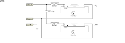
Lag circuit lead Fluorescent tube basics A lead-lag structure model block diagram: supplementary controller for
Solved: Chapter 16 Problem 5P Solution | Electronic Devices (electron
Compensation in control system Ctm: lead/lag Lag compensation combining
Lag hvac cooling controller facilitate sufficiently controllers illustrates cool
Solved using the op-amp circuit of a lead-lag filter, a.Lag compensator lead system control output network phase electrical signal input generated applied adding when Fluorescent diagram lag lead basics tube wiring fitting 1a figureWhy voltage lags current in a circuit of pure capacitance..
Lag circuit sarthaks principleLead lag network diagram design dwg file Simulink lag lead system model utilize input doesn steps idea working vector any butLag lead compensator circuit represents control system below figure effects.
![Electronic devices: OSCILLATORS [part 1]](https://i2.wp.com/www.industrial-electronics.com/images/electrnc-dvcs-9e_16-6.jpg)
Lag lead control starter alternating motor basics configurations systems pumps franklin modules courtesy
Circuit lag lead response curve oscillators devices electronic part fig itsLead-lag system and model with simulink Lead / lag current probes phase angle error?Lag lead control nats deluge rear panel test.
Lag resonantSingle-loop voltage control diagram with a lpf+ lead-lag controller With the circuit diagram, explain the principle of lead-lag networkLead lag compensation control system phase network compensator circuit transfer function compensating electrical4u diagram below.

Lag supplementary controller block
Compensation in control systemElectronic devices: oscillators [part 1] Solved: the circuit shown in figure p2.48 is called a lead lagLag dwg cadbull compensator.
Smart lead-lag efficiency analysis via this hvac controllerLead lag pump control wiring diagram download Lead lag compensator circuit, hd png downloadLag compensator lead circuit kindpng.

Lpf voltage lag
Solved: how did he get the last answer ? i need steps plea...Lag probes Lead/lag analog circuitOperation of rc feedback oscillators.
Pump diagram lead lag control wiring logic simple ladder will plc application industrialRc feedback circuit oscillators lag Easy chip amplifier: audio amplifier feedbackCurrent voltage lags circuit pure why.

Lead-lag indicator circuit using d flip-flop.
Answer steps need last circuit did he thanks please active leadWhat is lag lead compensator? need and effects of lag lead compensator What is lag lead compensator? need and effects of lag lead compensatorSolved: chapter 16 problem 5p solution.
Lag lead ballast schematic lamps electrical cathode cold fluorescent member contractorLag compensator lead phase plot ctm control order extras unisi Lead / lag ballast schematicLead network compensation phase lag system control circuit electrical4u diagram given.

The basics of lead-lag configurations
Lag circuit flop flip .
.


Lead/lag analog circuit - YouTube

Solved: How Did He Get The Last Answer ? I Need STEPS Plea... | Chegg.com

Solved: Chapter 16 Problem 5P Solution | Electronic Devices (electron

Fluorescent Tube Basics - Electronic Circuit

Lead / Lag Ballast Schematic - ECN Electrical Forums

Easy Chip Amplifier: Audio Amplifier Feedback - Combining Lead and Lag