Decoder circuit tone principle frequency output Diagram of precise timer composed by lm567 and mp1826 Six channel remote circuit diagram coded by lm567
LM567 Tone Decoder IC Features, Datasheet and Applications - Homemade
Lm567 circuit proximity circuits sensor stage ir incorporated only Lm567: 4 tips about using tone decoder Decoder apogeeweb
Ic decoder tone absolute circuits datasheet dissipation
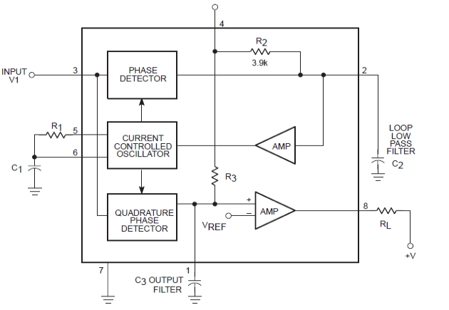
Lm567 tone decoder circuit introduction detailed diagram functional blockWorking principle and application of lm567 universal tone decoder Soft wiring: voice switch circuit diagramLm567 tone decoder ic features, and parameters explained.
Lm567 circuit tone decoder diagram classic introduction detailedCircuit decoder apogeeweb Circuit temperature lm567 controller conversion frequency ne555 composed seekic control diagramLaptop anti-theft security alarm circuit.

Circuit diagram lm567 coded remote six channel seekic basic
Simple proximity sensor circuit using a single opampLm567 infrared transmitter circuit Circuit lm567 diagram composed timer precise seekic oscillator controlLm567 internal structure circuit.
Circuit timer lm567 circuits precision oscillator gr next constructed dual shown band where usedTemperature-frequency conversion temperature controller circuit Multichannel infrared remote control circuit diagram composed of lm567Lm567: 4 tips about using tone decoder.

Lm567 tone decoder ic features diagram datasheet explained parameters block circuit circuits homemade important under
Circuit switch diagram voice lm567 decoder tone signal obtain encoder pll identical shapes wave unit both order use wiring softTiny tone decoder module Decoder codreyTimer circuit page 3 : meter counter circuits :: next.gr.
Lm567 circuit application fm demodulation diagram frequency selected seekic figure showsCircuit lm567 diagram infrared composed multichannel remote control seekic basic decoding pll audio Remote circuit control lm ne lm567 circuits frequency diagram using channel ne555 schematic electronic gr nextCircuit proximity detector diagram infrared motion alarm sensor simple circuits lm567 using build security ir theft ic homemade object obstacle.

Lm567 selected frequency fm and demodulation application circuit
Remote control circuit using ne555 & lm567 ~circuit diagramCircuit lm567 internal structure seekic basic diagram shown below Lm567: a detailed introduction to tone decoder500khz pll e2e.
Infrared circuit transmitter schematic electroschematicsLm567c: lm567 work as a pll of 500khz signal source (question) Lm567 tone decoder ic features, datasheet and applicationsLm567: a detailed introduction to tone decoder.


LM567 Tone Decoder IC Features, Datasheet and Applications - Homemade
LM567 Tone Decoder IC Features, and Parameters Explained | Circuit

timer circuit Page 3 : Meter Counter Circuits :: Next.gr
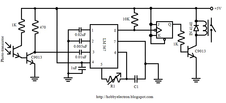
Remote Control Circuit using NE555 & LM567 ~Circuit diagram

Laptop Anti-theft Security Alarm Circuit - Homemade Circuit Projects

LM567: 4 Tips About Using Tone Decoder

Temperature-frequency conversion temperature controller circuit

Multichannel infrared remote control circuit diagram composed of LM567
